Utilities are usually pipes and cables and include electric, natural gas, telephone, fuel, water, and sewer lines. The ability of geophysical methods to detect utilities depends on the material from which the utility is made, its size, depth, and proximity to other sources of "noise" that may mask the signal from the detection equipment, and the electrical properties of the soil/bedrock in which the utility is buried.
The main methods used to locate utilities are magnetic, electromagnetic, and Ground Penetrating Radar (GPR). In addition, if a direct electrical connection to a utility made from conductive material can be made, the utility can be energized with an oscillating electrical field. Another method of energizing a buried metal pipe is to use inductive methods, in which a coil is placed above the pipe and oscillating current made to flow through the coil creating an oscillating magnetic field. This field then creates an oscillating current in the pipe. The resulting magnetic field from the utility can then be located and used to trace its path. Electrical cables with alternating electrical current flowing through (usually 60 Hz) them can be located by detecting the alternating magnetic field associated with the alternating electrical current. A more recent method is the development of an Acoustic Pipe Tracer that detects a sonic frequency transmitted through a plastic pipe.
If the utility is made from metal, electromagnetic methods can then be used. If the metal is ferromagnetic, magnetic methods can also be used. Non-metallic utilities, such as plastic, clay, and unreinforced concrete cannot be detected with electromagnetic -or magnetic methods. However, these, along with metal utilities, can be detected using GPR providing the conditions are appropriate and contrast is present between the electrical properties of the utility and the surrounding material; depth of investigation with GPR is significantly influenced by the local soil conditions and adequate depth of investigation may not be possible where clay rich soils are present.
Magnetic
Basic Concept: To be able to use magnetic methods, the utility must be constructed from, or have included in its construction, some ferromagnetic material. Ferromagnetic materials become magnetized by the earth's magnetic field, which then produce a secondary magnetic field. The resulting field at the ground surface is a combination of the earth's magnetic field and the secondary field from the utility. This creates an anomaly in the resultant magnetic field that can be detected by the geophysical instrument. A secondary magnetic field occurs when the small magnetic domains within the ferromagnetic material become predominantly aligned in one direction. If the object is a pipe, in the center of the pipe the magnetic fields from the domains cancel each other out and there is no resultant magnetic field. Thus, with ferromagnetic pipes, the strongest magnetic fields are produced at joints and the ends of the pipe.
Two kinds of magnetic detection instruments are used. One detects the strength of the magnetic field using one sensor, and the other detects the gradient of the magnetic field using two sensors. This instrument is called a Gradiometer. The magnetic field from a ferromagnetic object is illustrated in figure 178, and shows both the total magnetic field strength and the vertical gradient of the magnetic field for an object in the northern hemisphere. Since the inclination of the Earth's field changes with location, this will affect the magnetic field anomaly at that location.
In the United States, the Earth's magnetic field is dipping to the north at a moderately steep angle. The total magnetic field strength shows high values to the south of the object and negative values to the north. This is because the Earth's field induces north poles (positive values) as it enters the object and south poles (negative values) as it leaves the object. The vertical gradient of the magnetic field peaks over the top of the object and is flanked by negative values on either side. As can be seen from this diagram, the peak positive anomaly using the total magnetic field is not over the top of the object whereas the vertical gradient does peak over the top of the object. Thus, instruments that measure the vertical (or something close to vertical) magnetic gradient are better than instruments with a single sensor that only measure the total magnetic field and are able to more accurately locate the position of the object.
A magnetic locator, manufactured by the Schonstedt Instrument Company, is illustrated in figure 179. This instruments has two magnetic sensors and therefore responds to the gradient of the magnetic field.
M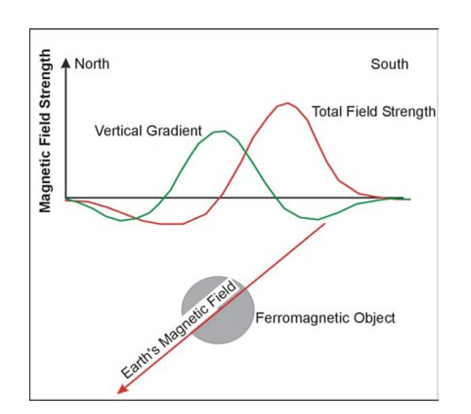
Figure 178. Magnetic field from a cylindrical object.
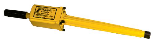
Figure 179. Magnetic locating instruments. (Schonstedt Instrument Company)
If the instrument is held vertically, then the vertical gradient of the magnetic field is measured. Figure 180 illustrates a magnetic detector (Gradiometer) showing the two sensors and the magnetic field from a ferromagnetic object.
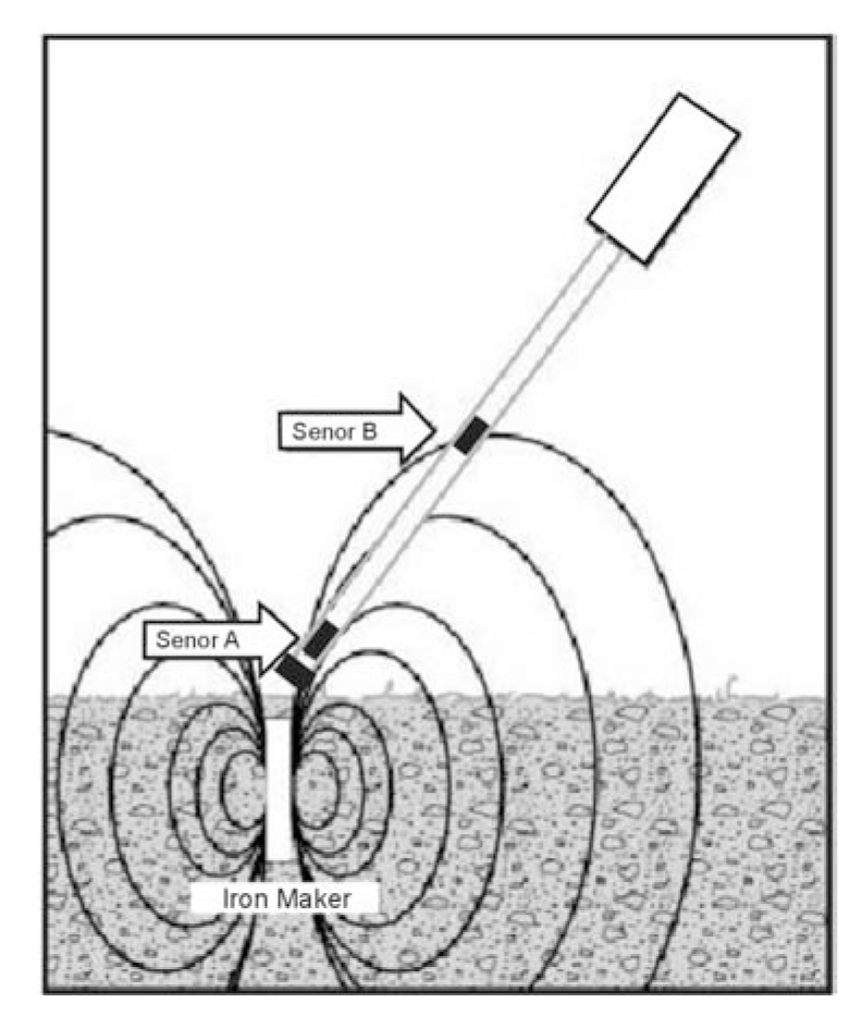
Figure 180. Magnetic locator using two sensors to measure the gradient.
Data Acquisition: Surveys are conducted by sweeping the instrument back and forth while walking at a slow pace. When using a gradiometer to measure the vertical gradient, the instrument should be held in a vertical position. Usually, these instruments have both a display and an audible sound when anomalies are found. No data processing can be done, or is needed, and no data are output from these instruments.
Data Interpretation: Data interpretation is not required since only the maximum signal (or maximum audible sound) is observed. Usually, spray paint marks will be placed on the ground where pipes are indicated by the instrument. These will typically be colored according to the American Public Works Standard, which are shown below:
| Conductor | Color |
| Electric power lines, cables or conduits | Red |
| Communication lines, cables or conduits | Orange |
| Gas, oil, petroleum or other gaseous material | Yellow |
| Storm and sanitary sewers; drain lines | Green |
| Water, irrigation or slurry lines | Blue |
Advantages: Magnetic locators are simple to operate and provide a field readout or signal when an anomaly is detected.
Limitations: Magnetic locators will only respond to metal that is ferromagnetic. Metals such as copper, aluminum, and stainless steel are not magnetized by the Earth's field and, therefore, do not produce a magnetic anomaly. The method will also not detect plastic, clay, or concrete pipes.
Electromagnetic
Basic Concept: Electromagnetic instruments for detecting utilities produce and sense electromagnetic fields. These instruments will only work if the utility is made from an electrically conductive material. The instruments produce the electromagnetic fields using a coil through which oscillating current is made to flow, thus producing an oscillating electromagnetic field. Another coil is used to sense this oscillating electromagnetic field. When a coil senses a changing electromagnetic field, a voltage is produced that can be displayed or activate a sound. If a utility is not made from metal, sometimes a metal tracer wire is placed along with the utility, thereby allowing electromagnetic instruments to be used to locate the utility.
This discussion of the instruments is divided into two parts. This is because there are a number of conventional electromagnetic utility-locating instruments that are commonly used, an example of which is presented above. In addition, more sophisticated geophysical instruments can be used for utility location. These instruments are most commonly used by geophysical companies, and less so by utility-locating companies.
The first section discusses the conventional utility-locating instruments and is titled Conventional Electromagnetic Utility Equipment. The second section is titled Geophysical Electromagnetic Utility Instruments.
Conventional Electromagnetic Utility-Locating Instruments
A utility detection instrument, manufactured by Metrotech Inc. that uses electromagnetic fields, is illustrated in figure 181.
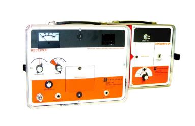
Figure 181. Utility-locating instrument. (Metrotech, Inc.)
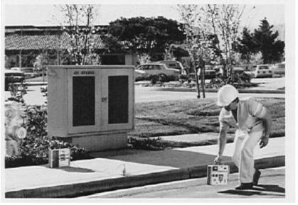
Figure 182. Metrotech electromagnetic pipe and cable locating instrument in use. (Metrotech, Inc.)
Such instruments have several modes of operation and can be used for both inductive and conductive pipe and cable locating. They also have passive mode in which they respond to the electromagnetic fields from 50/60 Hz signals. The equipment provides the ability to directly connect to a metal pipe, thus allowing the pipe to be energized. In addition, a clamp can be used to connect to a pipe where no direct connection is available. This clamp then inductively energizes the pipe and allows it to be located. Figure 182 shows the instrument being used. In this picture, the pipe is being energized inductively, and the operator then searches for anomalies using the receiver.
Data Acquisition: The design of a survey depends on the method of use. If a direct or inductive clamp can be attached to the pipe, the receiver portion of the instrument is used to trace the location of the pipe. If the location of some part of the pipe is known, the instrument can be used to inductively energize the pipe by placing the transmitting coil on the ground surface over the top of the pipe. If the location of the pipe is not known, and the investigation is to see if a pipe exists in a particular area, a system has to be devised to survey the area using numerous locations for the transmitting coil.
Data Processing: No data are output from the instrument, and no data processing is needed.
Data Interpretation: Interpretation is done by the operator who marks the ground with surveyor's spray paint where anomalies are observed. To locate a power line, the instrument is used in passive mode during which it detects 50/60 Hz magnetic field oscillations.
Advantages: The instruments are simple to use and provide anomaly indications while the survey is being conducted.
Limitations: The limitations are generally the depth of the utility, size of the utility (amount of metal), proximity to other local surface or buried metal, and local power line noise. Generally, these instruments are not significantly influenced by power line noise unless the power line is very close.
Geophysical Electromagnetic Utility Instruments
Basic Concept: Two instruments are commonly used by geophysical companies for utility locating. One is called the EM31, manufactured by Geonics Ltd. in Canada, and the other instrument, also manufactured by Geonics Ltd., is called an EM61. In order for electromagnetic methods to work, the utility must be electrically conductive.
EM31 Instrument
The EM31 instrument is shown in figure 183 and illustrates the most common method of use. This instrument uses two coils, one of which transmits electromagnetic energy at about 9.8 kHz, and the other coil receives the resulting signal. The coils are located at the ends of the boom. Because the instrument uses oscillating electromagnetic fields, this instrument is said to operate in the frequency domain. The newer EM31-MK2 model, shown in figure 183, incorporates the data logger into the control console.
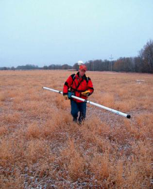
Figure 183. The EM31 MK2 instrument. (Geonics Ltd.)
The EM 31 can be used to locate buried pipes. It is particularly effective when a long pipe is to be located, since it produces a large response when a length of buried pipe extends on either side of the instrument. The instrument can be used in various modes. Its boom can be held parallel to the direction of travel or perpendicular. It can be used in a normal operating orientation (vertical dipole mode) or turned 90 degrees about its long axis (horizontal dipole mode). In the figure, the instrument is being used with its boom parallel to the direction of travel and in vertical dipole mode. This is the mode most often used for utility search surveys. The EM31 has a maximum depth of penetration of about 6 m. The depth at which it can detect a metal pipe will depend on the conductivity of the soil, local electromagnetic interference, and the amount of metal that the pipe contains. Thus, the diameter and wall thickness of the pipe each influence the data.
Data Acquisition: Surveys are conducted by walking at a slow pace normal to the expected utility orientation or if no information is available on the orientation of the utilities, data are acquired along a grid or while synced with GPS for locations contol. Data can be observed on a meter or are more typically stored on a data logger.
Data Interpretation: The data can be interpreted in the field by evaluating the shape of the anomalies. Just before a metal pipe is crossed, the readings increase, and then rapidly drop to a low value over the top of the pipe. Once the pipe has been crossed, the readings increase again before finally descending to non-anomalous values. Interpretation involves locating the anomaly described above on as many traverses as possible and then positioning a line through them to position the pipe.
Advantages: The EM31 is simple to use and provides a readout on the instrument allowing field evaluations of the anomalies. This instrument will generally find metal utilities to depths up to about 3-5 meters.
Limitations: Probably the largest limitation is that the electromagnetic fields generated by the instrument produce secondary fields, not only in utilities, but also in any other local metal objects, which then radiate their own field that is also detected by the instrument. The instrument is quite long and may be difficult to use in spatially restrictive areas.
EM61 Instrument
The EM61 transmits pulses of electromagnetic energy, rather than a continuous frequency as with the EM31, and as discussed above, and is called a time domain instrument. Figure 184 shows the EM61 recording data as it is being pushed by the operator.
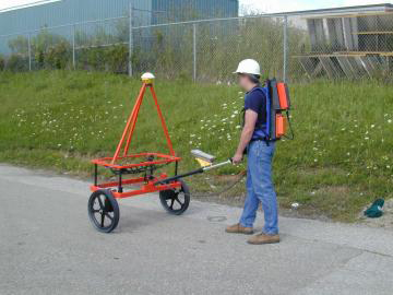
Figure 184. The EM61 instrument. (Geonics, Ltd.)
Two square-shaped coils are used. The lower coil transmits the electromagnetic energy, and both the lower and upper coils receive the resulting signals. The EM61 also has a hand-held version for surveys where the conventional EM61 may be too bulky and for shallower surveys. This instrument is shown in figure 185.
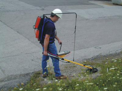
Figure 185. The EM61 hand held instrument. (Geonics, Ltd.)
Data Acquisition: As with the EM31, surveys are conducted by traversing across the area where buried pipes are thought to occur. The data can be observed using the display on a data logger and also stored in memory. The readings are presented in millivolts. Anomalies are simply higher millivolt values. Using the two coils, it is possible to minimize the influence of near-surface metal. This is because the lower coil has a greater response to surface metal than the upper coil. To evaluate whether the anomaly results from surface (or near- surface) metal, the amplitude of the signal from the upper coil is increased to what would be expected were it positioned at the level of the lower coil. If the anomaly observed results from surface metal, then the two amplitudes (amplified top and bottom coils) will be similar.
Advantages: The EM61 is an excellent instrument for locating metal in the top 2-3 meters of the ground surface.
Limitations: As with the EM31, the instrument produces electromagnetic fields and can energize local metal. However, this is a much less serious problem with this instrument than with the EM31. Because of its size, the EM61 may be difficult to use in confined areas. If that is the case, the hand-held EM61 can be used.
Ground Penetrating Radar
Basic Concept: Ground Penetrating Radar (GPR) is a technique that uses high frequency radar waves to image the subsurface. The GPR instrument consists of a recorder and a transmitting and receiving antenna. Different antennas use different frequencies, which usually vary between 25 and 2,600 MHz. Lower frequencies provide greater depth penetration but lower resolution. A schematic showing the transmitter and receiver along with the transmitted waves is illustrated in figure 111. The technique can be used where the overburden contains little clay or silt. An unsaturated overburden will provide the best penetration depths. If these conditions exist, then penetration depths may be tens of meters.
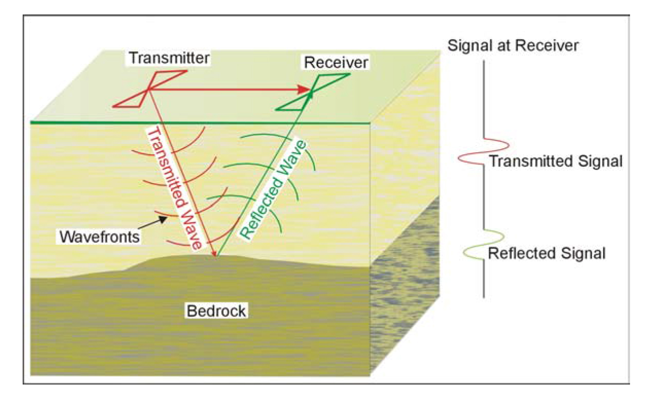
Figure 111. Ground Penetrating Radar system.
Several companies manufacture GPR equipment, including ImpulseRadar, IDS GeoRadar, Sensors & Software, Geophysical Survey Systems, Inc., (GSSI), Screening Eagle Technologies AG.
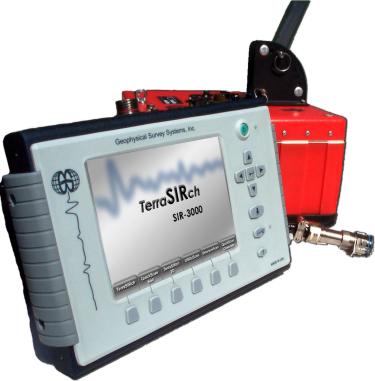
Figure 112. Ground Penetrating Radar instrument. (Geophysical Survey Systems, Inc.)
Figure 112 shows the data recording and system control for a GPR system. Any antenna supported by this instrument can be attached and used to collect data. A 400 MHz antenna that can be used with the above instrument is illustrated in figure 186.
Figure 186. 400 MHz Ground Penetrating Radar antenna. (Geophysical Survey Systems, Inc.)
This antenna is suited for fairly shallow applications to depths of about 3 meters and can be used to locate buried utilities.
Data Acquisition: GPR surveys are conducted by pulling the antenna across the ground surface at a normal walking pace. The recorder stores the data as well as presenting a picture of the recorded data on a screen. A typical GPR record searching for utilities is shown in figure 187 and illustrates anomalies from rebar and the utilities.
As can be seen, the rebar is seen as large numbers of small anomalies whereas the utilities are larger anomalies. It is worth noting that the GPR signal was able to penetrate through the rebar and present clear anomalies of the utilities.
Data Processing: The data are processed much like the processing done on reflection seismic data. Routines such as distance normalization, horizontal and vertical scaling, along with frequency filtering, are performed. However, depending on the data quality, this may not be necessary since the field records may be all that is needed to observe the utility.
Data Interpretation: To calculate the depth to the utility, the speed of the GPR signal in the soil at the site needs to be obtained. This can be estimated from handbook speeds for typical soil types, or, more optimally, it can be obtained in the field by conducting a small traverse across a buried feature whose depth is known.
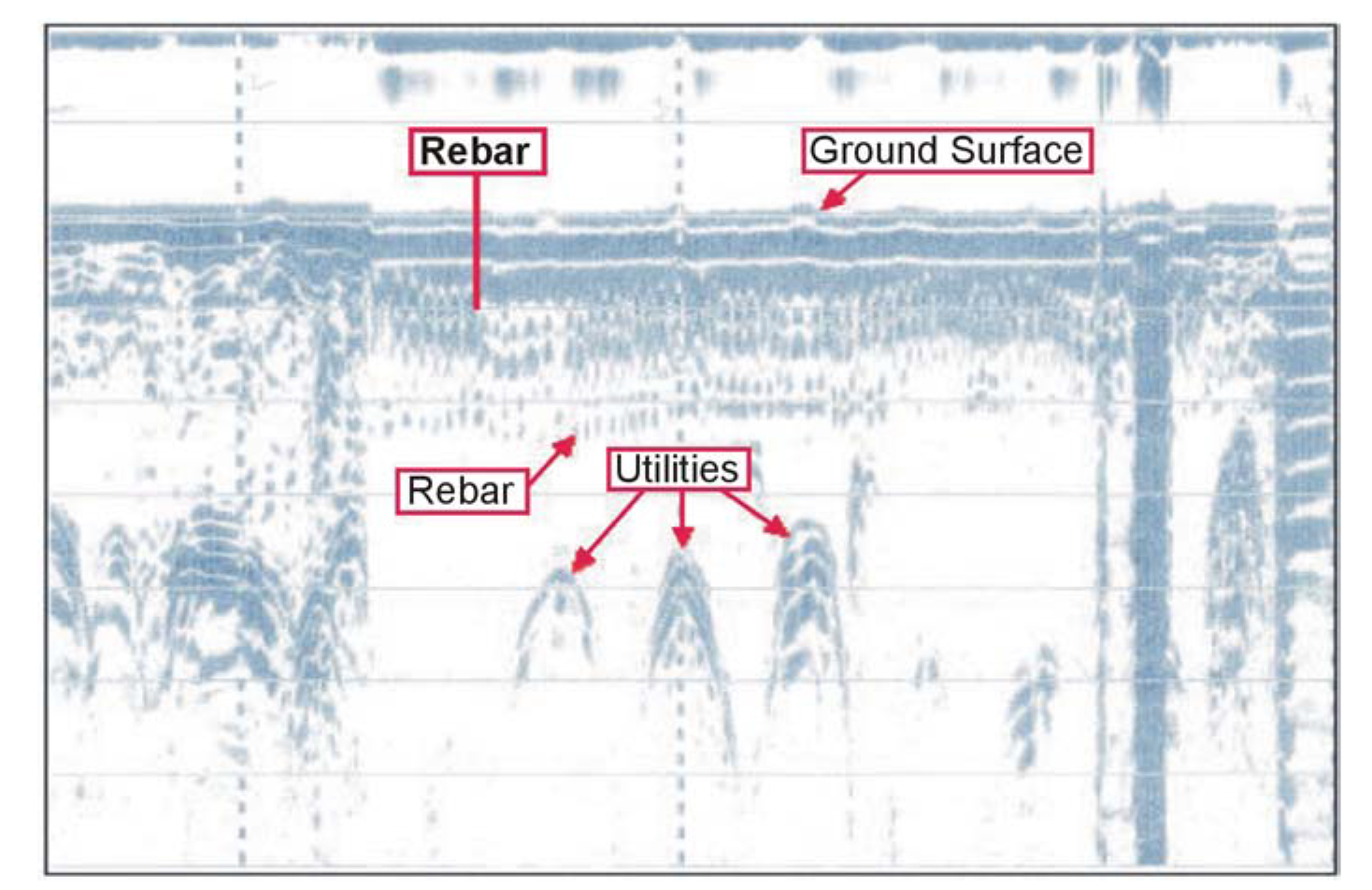
Figure 187. Ground Penetrating Radar data from a utility trench. (Golder Associates, Inc.)
Advantages: The GPR method provides a rapid technique for locating utilities. Since the data can be viewed on a screen on the instrument, the locations of anomalies can be marked on the ground at the time of the survey. For larger surveys, the data are typically processed and interpreted in the office and plans are generated showing the locations of detected utilities.
Limitations: The most limiting factor for GPR surveys is that their success is very site specific, and depends on having a contrast in the dielectric properties of the target compared to the host overburden, along with sufficient depth penetration to reach the target. However, it is likely that most utilities will provide the desired dielectric contrast needed, thus depth of penetration is probably the most important factor. Penetration depends on the frequency of the antenna, the conductivity of the overburden, and whether clay is present in the overburden. In addition, for lower frequencies, where the antenna is not shielded, reflections can occur from other objects. Generally, this should not be a problem for utility searches since most of the higher frequency antennas are shielded and are the ones used for buried utility surveys.
Acoustic Pipe Tracer
This instrument is able to locate buried plastic pipe and is used to locate buried plastic natural gas lines. An identifiable acoustic signal is introduced into the pipe. The receiver detects the sound waves that radiate from the pipe. An acoustic driver is used to put the signal into the pipe, and the sound is detected by sensors attached to a portable receiver.